Reversing and Exploiting Samsung's Neural Processing Unit
Post by Maxime Peterlin
This series of blogposts aims to describe and explain the internals of a recent addition to Samsung's system-on-chips, namely their Neural Processing Unit. The first part digs into the internals of the NPU and the second one focuses on the exploitation of some vulnerabilities we found in the implementation. If you're interested in reversing a minimal OS, want to understand how Android interacts with peripherals and do exploitation like it's the early 2000's, this series might be for you.
Table Of Contents
- Introduction
- Environment
- Initialization of the NPU Driver and Loading of the NPU Firmware
- Firmware Extraction and Reverse Engineering
- NPU Operating System
- Interacting with the NPU
- Conclusion
- References
Introduction
A neural processor or a neural processing unit (NPU) is a specialized circuit that implements all the necessary control and arithmetic logic necessary to execute machine learning algorithms, typically by operating on predictive models such as artificial neural networks (ANNs) or random forests (RFs).
Source: https://en.wikichip.org/wiki/neural_processor
At the time of writing, Samsung has released four SoCs embedding an NPU:
- Exynos 9820
- Exynos 9825
- Exynos 980
- Exynos 990
This article focuses primarily on the Exynos 990 found on Galaxy S20 devices; although, most of the concepts discussed here also apply to other SoCs.
An additional chip on a SoC often means dedicated firmware and therefore a larger attack surface. Google Project Zero has disclosed and exploited vulnerabilities affecting the Samsung NPU drivers and pointed out that it can be accessed with the untrusted_app SELinux context. These issues have now been patched and the SELinux contexts which have access to the NPU are more strict.
However there is currently no information on the actual NPU firmware implementation, how it works, and how it interacts with the rest of the system. This blogpost tries to answer some of those questions.
Environment
This analysis was performed on a rooted Samsung Galaxy S20 SM-G980F using the firmware G980FXXS5CTL5. It's important for the device to be rooted since we want access to dmesg and the NPU driver (which is not possible from the shell on the newest versions since Project Zero's disclosure).
It's not uncommon for Samsung to provide debug information in the components they develop and the NPU is no exception. Logs in dmesg are extremely verbose for both the NPU driver and firmware, as you can see below.
x1s:/ # sysctl -w kernel.kptr_restrict=1
x1s:/ # dmesg -w | grep "NPU:"
[102.037911] [Exynos][NPU][NOTICE]: NPU:[*]npu_debug_open(221):start in npu_debug open
[102.037928] [Exynos][NPU][NOTICE]: NPU:[*]npu_debug_open(222):complete in npu_debug open
[102.037936] [Exynos][NPU][NOTICE]: NPU:[*]npu_log_open(1335):start in npu_log_open
[102.037943] [Exynos][NPU][NOTICE]: NPU:[*]npu_log_open(1336):complete in npu_log_open
[102.037951] [Exynos][NPU][NOTICE]: NPU:[*]npu_util_memdump_open(319):start in npu_util_memdump_open
[102.037958] [Exynos][NPU][NOTICE]: NPU:[*]npu_util_memdump_open(344):complete in npu_util_memdump_open
[102.037966] [Exynos][NPU][NOTICE]: NPU:[*]npu_scheduler_open(1458):done
[102.039801] [Exynos][NPU][NOTICE]: NPU:[*]npu_system_resume(387):wake_lock, now(1)
[102.039813] [Exynos][NPU][NOTICE]: NPU:[*]npu_system_alloc_fw_dram_log_buf(93):start: initialization.
[102.040957] [Exynos][NPU][NOTICE]: NPU:[*]npu_system_alloc_fw_dram_log_buf(103):DRAM log buffer for kernel: size(2097152) / dv(0x0000000080000000) / kv(ffffff802ca85000)
There are also debugfs entries that can be used to retrieve information about the NPU (the NPU driver has to be opened at least once for all of them to appear).
x1s:/ # ls -la /d/npu/
total 0
drwxr-xr-x  2 root   root   0 2021-01-30 18:18 .
drwxr-xr-x 63 system system 0 1970-01-01 01:00 ..
-rw-------  1 root   root   0 2021-01-30 18:21 SRAM-IDP
-rw-------  1 root   root   0 2021-01-30 18:21 SRAM-TCU
-r--------  1 root   root   0 2021-01-30 18:18 dev-log
-r--------  1 root   root   0 2021-01-30 18:21 fw-log-SRAM
-r--------  1 root   root   0 2021-01-30 18:18 fw-profile
-r--------  1 root   root   0 2021-01-30 18:18 fw-report
-rw-------  1 root   root   0 2021-01-30 18:18 idiot
-r--------  1 root   root   0 2021-01-30 18:18 proto-drv-dump
-r--------  1 root   root   0 2021-01-30 18:18 result-golden-match
--w-------  1 root   root   0 2021-01-30 18:18 set-golden-desc
All of this information is very helpful when trying to reverse engineer the NPU and understand the underlying concepts.
Initialization of the NPU Driver and Loading of the NPU Firmware
Loading of the NPU Driver
Before we can start analyzing the firmware in our favorite disassembler, we first need to locate it. This section explains how the NPU driver is started by the kernel and the operations it performs to load the firmware on the dedicated chip.
The initialization starts in the file drivers/vision/npu/core/npu-device.c with a call to npu_device_init when the kernel is booting.
static int __init npu_device_init(void)
{
    int ret = platform_driver_register(&npu_driver);

    /* [...] */
}

/* [...] */
late_initcall(npu_device_init);
npu_device_init calls platform_driver_register and passes it the following structure as an argument:
static struct platform_driver npu_driver = {
    .probe  = npu_device_probe,
    .remove = npu_device_remove,
    .driver = {
        .name   = "exynos-npu",
        .owner  = THIS_MODULE,
        .pm = &npu_pm_ops,
        .of_match_table = of_match_ptr(exynos_npu_match),
    },
};
When the module is loaded by the kernel, the function npu_device_probe is called (error checks were removed from the following snippet for clarity).
static int npu_device_probe(struct platform_device *pdev)
{
    int ret = 0;
    struct device *dev;
    struct npu_device *device;

    dev = &pdev->dev;
    device = devm_kzalloc(dev, sizeof(*device), GFP_KERNEL);
    device->dev = dev;

    ret = npu_system_probe(&device->system, pdev);
    ret = npu_debug_probe(device);
    ret = npu_log_probe(device);
    ret = npu_vertex_probe(&device->vertex, dev);
    ret = proto_drv_probe(device);
    ret = npu_sessionmgr_probe(&device->sessionmgr);

#ifdef CONFIG_NPU_GOLDEN_MATCH
    ret = register_golden_matcher(dev);
#endif

#ifdef CONFIG_NPU_LOOPBACK
    ret = mailbox_mgr_mock_probe(device);
#endif
    ret = npu_profile_probe(&device->system);
    ret = iovmm_activate(dev);
    iovmm_set_fault_handler(dev, npu_iommu_fault_handler, device);

    dev_set_drvdata(dev, device);

    ret = 0;
    probe_info("complete in %s\n", __func__);

    goto ok_exit;

err_exit:
    probe_err("error on %s ret(%d)\n", __func__, ret);
ok_exit:
    return ret;

}
Essentially, npu_device_probe initializes the following components:
- interrupts (using the corresponding DTS file)
- shared memory mappings
- relevant IO devices mappings
- npu interface and mailbox
- firmware binary paths
/data/NPU.binand/vendor/firmware/NPU.bin- If these two paths don't exist, the device will try to load it from
npu/NPU.bin, which is embedded inside the kernel image
- debugfs entries
- vertex objects
- It sets, among other things, the file operations and ioctl handlers for the device:
- File operations:
npu_vertex_fops - Ioctl handlers:
npu_vertex_ioctl_ops
- File operations:
- It sets, among other things, the file operations and ioctl handlers for the device:
- session manager
- iovmm
It's not too important to understand the details of these operations for the moment. Some of them are explained later in this article when it becomes relevant. For now, let's have a look at how the NPU is loaded onto the chip and started by the kernel.
NPU Driver Power Management and Firmware Loading
The npu_driver structure mentioned earlier also registers npu_pm_ops as its power management operation handlers.
static const struct dev_pm_ops npu_pm_ops = {
    SET_SYSTEM_SLEEP_PM_OPS(npu_device_suspend, npu_device_resume)
    SET_RUNTIME_PM_OPS(npu_device_runtime_suspend, npu_device_runtime_resume, NULL)
};
When the device needs to start the NPU, it triggers a call to npu_device_runtime_resume in the power management system, and then to npu_system_resume (the snippet below was simplified for clarity).
int npu_system_resume(struct npu_system *system, u32 mode)
{
    /* [...] */

    /* Loads the firmware in memory from the filesystem */
    ret = npu_firmware_load(system);

    /* Starts the NPU firmware */
    ret = npu_system_soc_resume(system, mode);

    /* Opens an interface to the NPU */
    ret = npu_interface_open(system);

    /* [...] */

    return ret;
}
npu_firmware_load calls npu_firmware_file_read which tries to read the firmware from /data/NPU.bin or /vendor/firmware/NPU.bin. If none of those files exist, it tries to read it from the kernel filesystem at npu/NPU.bin. The content of the file is then copied into an iomem region at system->fw_npu_memory_buffer->vaddr.
The iomem region for the firmware is FW_DRAM and is defined in arch/arm64/boot/dts/exynos/exynos9830.dts which is parsed by init_iomem_area during the initialization of the driver. In the NPU's address space, this region starts at physical address 0x50000000 and has a size of 0xe0000. The corresponding address in the kernel is allocated dynamically.
Note: IOMMU allocations are explained in more detail in the section Sharing Resources Between the Kernel and the NPU.
Finally npu_system_soc_resume is called to start the NPU using npu_cpu_on.
The NPU is started when /dev/vertex10 is opened and stopped when it is closed. When opening the device you should then see logs in dmesg similar to the following ones:
[123.007254] NPU:[*]npu_debug_open(221):start in npu_debug open
[123.007264] NPU:[*]npu_debug_open(222):complete in npu_debug open
[123.007269] NPU:[*]npu_log_open(1152):start in npu_log_open
[123.007274] NPU:[*]npu_log_open(1153):complete in npu_log_open
[123.007279] NPU:[*]npu_util_memdump_open(317):start in npu_util_memdump_open
[123.007282] NPU:[*]npu_util_memdump_open(342):complete in npu_util_memdump_open
[123.007820] NPU:[*]npu_system_resume(346):wake_lock, now(1)
[123.007827] NPU:[*]npu_system_alloc_fw_dram_log_buf(93):start: initialization.
[123.009277] NPU:[*]npu_system_alloc_fw_dram_log_buf(103):DRAM log buffer for firmware: size(2097152) / dv(0x0000000080000000) / kv(ffffff803db75000)
[123.009293] NPU:[*]npu_store_log_init(216):Store log memory initialized : ffffff803db75000[Len = 2097152]
[123.009303] NPU:[*]npu_fw_test_initialize(290):fw_test : initialized.
[123.009309] NPU:[*]npu_system_alloc_fw_dram_log_buf(125):complete : initialization.
[123.009315] NPU:[*]npu_firmware_load(540):Firmware load : Start
[123.023161] NPU:[*]__npu_binary_read(215):success of binay(npu/NPU.bin, 475349) apply.
[123.023196] NPU:[*]print_fw_signature(111):NPU Firmware signature : 009:094 2019/04/25 14:56:44
[123.023210] NPU:[*]npu_firmware_load(572):complete in npu_firmware_load
[123.023233] NPU:[*]print_iomem_area(466):\x01c(TCU_SRAM) Phy(0x19200000)-(0x19280000) Virt(ffffff802b900000) Size(524288)
[123.023243] NPU:[*]print_iomem_area(466):\x01c(IDP_SRAM) Phy(0x19300000)-(0x19400000) Virt(ffffff802ba00000) Size(1048576)
[123.023251] NPU:[*]print_iomem_area(466):\x01c(SFR_NPU0) Phy(0x17900000)-(0x17a00000) Virt(ffffff802bc00000) Size(1048576)
[123.023259] NPU:[*]print_iomem_area(466):\x01c(SFR_NPU1) Phy(0x17a00000)-(0x17af0000) Virt(ffffff802be00000) Size(983040)
[123.023270] NPU:[*]print_iomem_area(466):\x01c( PMU_NPU) Phy(0x15861d00)-(0x15861e00) Virt(ffffff8010eedd00) Size(256)
[123.023279] NPU:[*]print_iomem_area(466):\x01c(PMU_NCPU) Phy(0x15862f00)-(0x15863000) Virt(ffffff8010ef5f00) Size(256)
[123.023288] NPU:[*]print_iomem_area(466):\x01c(MBOX_SFR) Phy(0x178b0000)-(0x178b017c) Virt(ffffff8010efd000) Size(380)
[123.023367] NPU:[*]npu_cpu_on(729):start in npu_cpu_on
[123.023420] NPU:[*]npu_cpu_on(736):complete in npu_cpu_on
[123.023445] NPU:[*]npu_system_soc_resume(513):CLKGate1_DRCG_EN_write_enable
[123.023451] NPU:[*]CLKGate4_IP_HWACG_qch_disable(261):start CLKGate4_IP_HWACG_qch_disable
[123.024797] NPU log sync [60544]
[123.024894] NPU:[*]npu_system_soc_resume(525):CLKGate5_IP_DRCG_EN_write_enable
[123.025842] NPU:[*]mailbox_init(46):mailbox initialize: start, header base at ffffff802b97ff7c
[123.025852] NPU:[*]mailbox_init(47):mailbox initialize: wait for firmware boot signature.
[123.036810] NPU:[*]mailbox_init(53):header signature \x09: C0FFEE0
[123.036821] NPU:[*]mailbox_init(76):header version \x09: 00060004
[123.036826] NPU:[*]mailbox_init(83):init. success in NPU mailbox
[123.036831] NPU:[*]npu_device_runtime_resume(582):npu_device_runtime_resume():0
Firmware Extraction and Reverse Engineering
At this stage, we know how the NPU is started and where is firmware is located. The next step is now to extract the binary from the device.
There are two different types of firmware, depending on the type of CPU used for the NPU.
- Exynos 9820 SoCs (Galaxy S10 models) use ARMv7 Cortex-M cores.
- Exynos 990 SoCs (Galaxy S20 models) use ARMv7 Cortex-A cores.
Both firmwares are very similar in their implementation, but there are still differences, especially during the initialization phase. In this article, we focus on the ARMv7-A implementation.
As explained in the previous section, the firmware can be found at three possible locations:
/data/NPU.bin/vendor/firmware/NPU.binnpu/NPU.bin(extracted from the kernel image)
On the Galaxy S20, the NPU firmware is embedded inside the kernel image. It's possible to extract it from a rooted device using the following tool: npu_firmware_extractor.py and passing it the --cortex-a flag.
$ python3 npu_firmware_extractor.py -d . --cortex-a
[+] Connection to the device using ADB.
[+] Pulling the kernel from the device to the host.
[+] Extracting the firmware.
[+] Done.
$ ll
-rw-r--r--  1 lyte  staff   464K  4 jan 16:30 NPU.bin
-rw-r--r--  1 lyte  staff    55M  4 jan 16:30 boot.img
-rw-r--r--  1 lyte  staff   3,6K  4 jan 16:29 npu_firmware_extractor.py
There is also the possibility of dumping the SRAM memory range allocated for the NPU firmware. Earlier, we have shown different debugfs entries. Among these, there is SRAM-TCU which can be used to dump the NPU's code and data at runtime. While this file works on the Samsung S10, the kernel will panic if you try to open it on the Samsung S20.
It's possible to fix this issue by recompiling a new version of the kernel. Samsung's kernel source code can be downloaded by following this link, searching for SM-G980F and downloading the source code for the version G980FXXU5CTL1.
The following patch can be applied to the kernel to fix these issues:
diff --git a/drivers/vision/npu/core/npu-util-memdump.c b/drivers/vision/npu/core/npu-util-memdump.c
index 5711bbb..8749701 100755
--- a/drivers/vision/npu/core/npu-util-memdump.c
+++ b/drivers/vision/npu/core/npu-util-memdump.c
@@ -109,12 +109,13 @@ int ram_dump_fault_listner(struct npu_device *npu)
 {
    int ret = 0;
    struct npu_system *system = &npu->system;
-   u32 *tcu_dump_addr = kzalloc(system->tcu_sram.size, GFP_ATOMIC);
+   u32 *tcu_dump_addr = kzalloc(system->fw_npu_memory_buffer->size, GFP_ATOMIC);
    u32 *idp_dump_addr = kzalloc(system->idp_sram.size, GFP_ATOMIC);

    if (tcu_dump_addr) {
-       memcpy_fromio(tcu_dump_addr, system->tcu_sram.vaddr, system->tcu_sram.size);
-       pr_err("NPU TCU SRAM dump - %pK / %paB\n", tcu_dump_addr, &system->tcu_sram.size);
+       memcpy_fromio(tcu_dump_addr, system->fw_npu_memory_buffer->vaddr,
+           system->fw_npu_memory_buffer->size);
+       pr_err("NPU TCU SRAM dump - %pK / %paB\n", tcu_dump_addr, &system->fw_npu_memory_buffer->size);
    } else {
        pr_err("tcu_dump_addr is NULL\n");
        ret= -ENOMEM;
@@ -281,20 +282,22 @@ DECLARE_NPU_SRAM_DUMP(idp);
 int npu_util_memdump_probe(struct npu_system *system)
 {
    BUG_ON(!system);
-   BUG_ON(!system->tcu_sram.vaddr);
+   BUG_ON(!system->fw_npu_memory_buffer->vaddr);
 #ifdef CONFIG_NPU_LOOPBACK
    return 0;
 #endif
    atomic_set(&npu_memdump.registered, 0);
-   npu_memdump.tcu_sram = system->tcu_sram;
+   npu_memdump.tcu_sram.vaddr = system->fw_npu_memory_buffer->vaddr;
+   npu_memdump.tcu_sram.paddr = system->fw_npu_memory_buffer->paddr;
+   npu_memdump.tcu_sram.size = system->fw_npu_memory_buffer->size;
    npu_memdump.idp_sram = system->idp_sram;
-   probe_info("%s: paddr = %08x\n", FW_MEM_LOG_NAME,
-          system->tcu_sram.paddr + MEM_LOG_OFFSET
+   probe_info("%s: paddr = %08llx\n", FW_MEM_LOG_NAME,
+          system->fw_npu_memory_buffer->paddr + MEM_LOG_OFFSET
           );
 #ifdef CONFIG_EXYNOS_NPU_DEBUG_SRAM_DUMP
-   probe_info("%s: paddr = %08x\n", TCU_SRAM_DUMP_SYSFS_NAME,
-       system->tcu_sram.paddr);
-   tcu_sram_dump_size = system->tcu_sram.size;
+   probe_info("%s: paddr = %08llx\n", TCU_SRAM_DUMP_SYSFS_NAME,
+       system->fw_npu_memory_buffer->paddr);
+   tcu_sram_dump_size = system->fw_npu_memory_buffer->size;
    probe_info("%s: paddr = %08x\n", IDP_SRAM_DUMP_SYSFS_NAME,
        system->idp_sram.paddr);
    idp_sram_dump_size = system->idp_sram.size;
After recompiling and booting the kernel, it's possible to dump the NPU's address space using npu_sram_dumper.
$ make run
These binaries can now be loaded into IDA or any other disassembler. For both Cortex-M and Cortex-A, the base address is 0. If you want to follow along, here's a link to the binary that is analyzed in this article: npu_s20_binary.bin. However, this is just the plain firmware, if you also want some of the values initialized at runtime, you can have a look at npu_s20_dump.bin.
NPU Operating System
The NPU firmware implements a minimal operating system capable of handling the different requests from the kernel and sending back the results. This section gives an overview of the different components comprising the OS and tries to highlight their interactions.
A good chunk of the code presented in this section was reverse engineered and is available here. All those snippets of code try to stay as true as possible to the original logic implemented, but there might be some deviations for the sake of simplicity (e.g. removing critical section wrappers that would multiply the number of functions by almost two). Also, even though this section explains the inner workings of components deemed relevant, readers interested in the actual implementations are encouraged to read the equivalent C code, since most of it is commented.
NPU Firmware Initialization
Since we're dealing with a 32-bit Cortex-A CPU, the exception vector is based on the following format:
Offset | Handler
0x00   | Reset
0x04   | Undefined Instruction
0x08   | Supervisor Call
0x0c   | Prefetch Abort
0x10   | Data Abort
0x14   | Not used
0x18   | IRQ interrupt
0x1c   | FIQ interrupt
When the NPU starts, the first instruction executed at offset 0 jumps to the function reset_handler.
Basically, this function is going to:
- Enable NEON instructions;
- Make sure we're running in supervisor mode;
- Initialize the page tables and activate the MPU;
- Set the stack pointer for the different CPU mode (e.g. abort, FIQ, etc.);
- Call the
mainfunction.
Before we jump to the main function of the NPU, let's have a look at how page tables are set by the firmware to get an overview of memory mappings.
The function responsible for these operations is init_memory_management. If you look at the code, you might notice that it sets SCR to 0, which means that the NPU could potentially access secure memory. Unfortunately for attackers, this component is not configured on the AXI bus as secure, which means that access to secure memory will result in an hardware exception.
int init_memory_management() {
    /* [...] */

    /*
     * SCR - Secure Configuration Register
     *
     *     NS=0b0: Secure mode enabled.
     *     ...
     */
    write_scr(0);

    return init_page_tables();
}
The function then goes on to call init_page_tables. This method calls SetTransTable to actually create the level 1 and level 2 page table entries. init_page_tables then writes the L1 page table address to TTBR0 and clean the caches .
int init_page_tables() {
    /* [...] */

    SetTransTable(0, 0x50000000, 0x1D000, 0, 0x180D);
    SetTransTable(0x1D000, 0x5001D000, 0x3000, 0, 0x180D);
    SetTransTable(0x20000, 0x50020000, 0xC000, 0, 0x180D);
    SetTransTable(0x2C000, 0x5002C000, 0x4000, 0, 0x180D);
    SetTransTable(0x30000, 0x50030000, 0x1000, 0, 0x180D);
    SetTransTable(0x31000, 0x50031000, 0x2800, 0, 0x1C0D);
    SetTransTable(0x33800, 0x50033800, 0x1000, 0, 0x1C0D);
    SetTransTable(0x34800, 0x50034800, 0x1000, 0, 0x1C0D);
    SetTransTable(0x35800, 0x50035800, 0x1000, 0, 0x1C0D);
    SetTransTable(0x36800, 0x50036800, 0x1000, 0, 0x1C0D);
    SetTransTable(0x37800, 0x50037800, 0x5000, 0, 0x1C0D);
    SetTransTable(0x3C800, 0x5003C800, 0x2B800, 0, 0x1C0D);
    SetTransTable(0x68000, 0x50068000, 0x18000, 0, 0x1C01);
    SetTransTable(0x80000, 0x50080000, 0x60000, 0, 0x1C0D);
    SetTransTable(0x10000000, 0x10000000, 0x10000000, 0, 0x816);
    SetTransTable(0x40100000, 0x40100000, 0x100000, 0, 0xC16);
    SetTransTable(0x40300000, 0x40300000, 0x100000, 0, 0x1C0E);
    SetTransTable(0x40600000, 0x40600000, 0x100000, 0, 0x1C12);
    SetTransTable(0x40200000, 0x40200000, 0x100000, 0, 0xC16);
    SetTransTable(0x40300000, 0x40300000, 0x100000, 0, 0x1C0E);
    SetTransTable(0x40700000, 0x40700000, 0x100000, 0, 0x1C12);
    SetTransTable(0x50100000, 0x50100000, 0x200000, 0, 0x1C02);
    SetTransTable(0x50000000, 0x50000000, 0xE0000, 0, 0x1C02);
    SetTransTable(0x40400000, 0x40400000, 0x100000, 0, 0x1C02);
    SetTransTable(0x40000000, 0x40000000, 0x100000, 0, 0xC16);
    SetTransTable(0x80000000, 0x80000000, 0x60000000, 0, 0x1C02);

    /* [...] */
Note: this link provides a nice refresher on how page tables work on ARMv7 and can be useful to comprehend the operations performed in SetTransTable.
After reversing SetTransTable, it's now very easy to retrieve all details on the NPU memory mappings, as shown in the table below.
| Type | Virtual Address | Physical Address | Size | PXN | XN | NS | AP | B | C | S |
|---|---|---|---|---|---|---|---|---|---|---|
| Short Desc. | 0x00000000 | 0x50000000 | 0x0001d000 | N | N | N | Writes at PL0 generate Permission faults | Y | Y | N |
| Short Desc. | 0x0001d000 | 0x5001d000 | 0x00003000 | N | N | N | Writes at PL0 generate Permission faults | Y | Y | N |
| Short Desc. | 0x00020000 | 0x50020000 | 0x0000c000 | N | N | N | Writes at PL0 generate Permission faults | Y | Y | N |
| Short Desc. | 0x0002c000 | 0x5002c000 | 0x00004000 | N | N | N | Writes at PL0 generate Permission faults | Y | Y | N |
| Short Desc. | 0x00030000 | 0x50030000 | 0x00001000 | N | N | N | Writes at PL0 generate Permission faults | Y | Y | N |
| Short Desc. | 0x00031000 | 0x50031000 | 0x00002800 | N | N | N | Full access | Y | Y | N |
| Short Desc. | 0x00033800 | 0x50033800 | 0x00001000 | N | N | N | Full access | Y | Y | N |
| Short Desc. | 0x00034800 | 0x50034800 | 0x00001000 | N | N | N | Full access | Y | Y | N |
| Short Desc. | 0x00035800 | 0x50035800 | 0x00001000 | N | N | N | Full access | Y | Y | N |
| Short Desc. | 0x00036800 | 0x50036800 | 0x00001000 | N | N | N | Full access | Y | Y | N |
| Short Desc. | 0x00037800 | 0x50037800 | 0x00005000 | N | N | N | Full access | Y | Y | N |
| Short Desc. | 0x0003c800 | 0x5003c800 | 0x0002b800 | N | N | N | Full access | Y | Y | N |
| Short Desc. | 0x00068000 | 0x50068000 | 0x00018000 | N | N | N | Full access | N | N | N |
| Short Desc. | 0x00080000 | 0x50080000 | 0x00060000 | N | N | N | Full access | Y | Y | N |
| Section | 0x10000000 | 0x10000000 | 0x10000000 | N | Y | N | Writes at PL0 generate Permission faults | Y | N | N |
| Section | 0x40100000 | 0x40100000 | 0x00100000 | N | Y | N | Full access | Y | N | N |
| Section | 0x40300000 | 0x40300000 | 0x00100000 | N | N | N | Full access | Y | Y | N |
| Section | 0x40600000 | 0x40600000 | 0x00100000 | N | Y | N | Full access | N | N | N |
| Section | 0x40200000 | 0x40200000 | 0x00100000 | N | Y | N | Full access | Y | N | N |
| Section | 0x40300000 | 0x40300000 | 0x00100000 | N | N | N | Full access | Y | Y | N |
| Section | 0x40700000 | 0x40700000 | 0x00100000 | N | Y | N | Full access | N | N | N |
| Section | 0x50100000 | 0x50100000 | 0x00200000 | N | N | N | Full access | N | N | N |
| Section | 0x50000000 | 0x50000000 | 0x000e0000 | N | N | N | Full access | N | N | N |
| Section | 0x40400000 | 0x40400000 | 0x00100000 | N | N | N | Full access | N | N | N |
| Section | 0x40000000 | 0x40000000 | 0x00100000 | N | Y | N | Full access | Y | N | N |
| Section | 0x80000000 | 0x80000000 | 0x60000000 | N | N | N | Full access | N | N | N |
As you can see, there are very few sections that use software mitigations, which will come in handy when we will exploit the NPU in the next article.
Main Function
After configuring the NPU's address space and other CPU-related settings, let's analyze the boot process of the operating system, starting with main.
void main() {
    heap_init();
    arm_init();
    timers_init();
    events_init();
    semaphores_init();
    scheduler_init();
    comm_channels_init();
    run_native_tasks(0x37800);

    /* Should not be reached */
    abort();
}
main doesn't do much by itself other than calling all the initialization routines to configure the heap, timers, etc. We'll look at each of these functions, and the subsystems they initialize, in the following sections.
Heap
The heap is set up in the function heap_init. The idea behind the initialization of the heap is pretty simple. To be able to allocate memory from this memory region, it first needs to be marked as freed. To do this, the OS defines the whole heap as a chunk. A heap chunk is based on the following structure:
struct heap_chunk {
    u32 size;
    struct heap_chunk *next;
};
The OS then sets the size of this first chunk to the size of the whole heap (i.e. HEAP_END_ADDR - HEAP_START_ADDR = 0x60000), before finally freeing this chunk. This process is illustrated in the figure below.
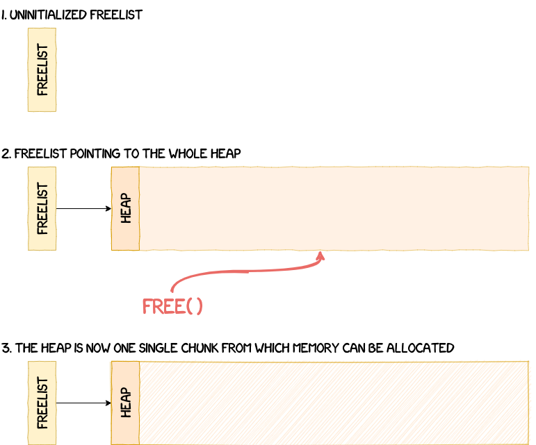
After this initialization step, it's now possible to manage memory dynamically using functions such as malloc and free.
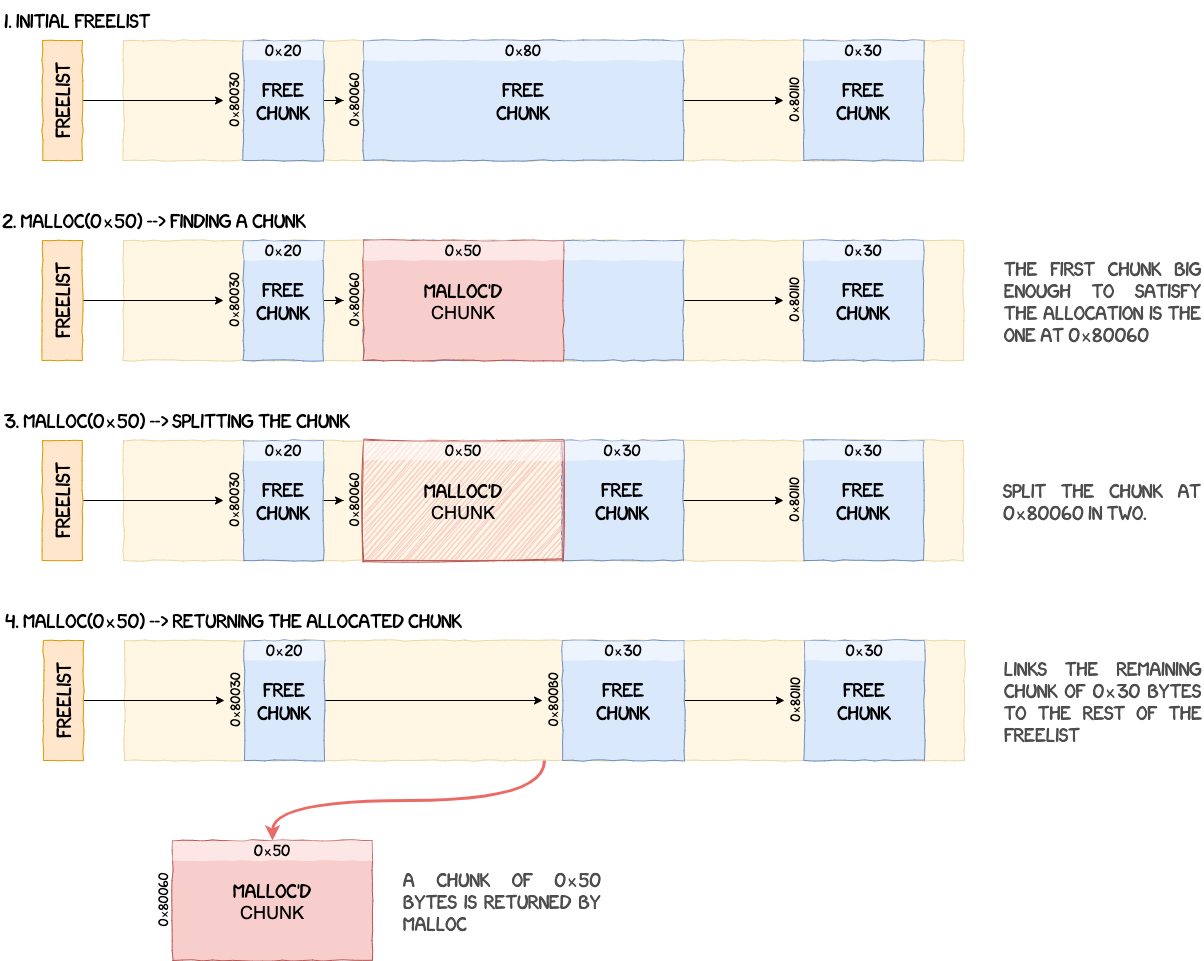
To allocate memory from the heap, malloc iterates through the single-linked freelist to find the first chunk big enough to satisfy the size constraints of the allocation. Chunks are sorted using their address and if the chunk found is bigger than what the OS requested, it is split in two, returning a chunk with the requested size and creating a new chunk with what's remaining.
For example, if the OS calls malloc(0x50) and a chunk of size 0x80 is found in the freelist, two new chunks are created:
- one chunk of
0x50bytes returned to the OS; - one chunk of
0x30bytes linked back into the freelist.
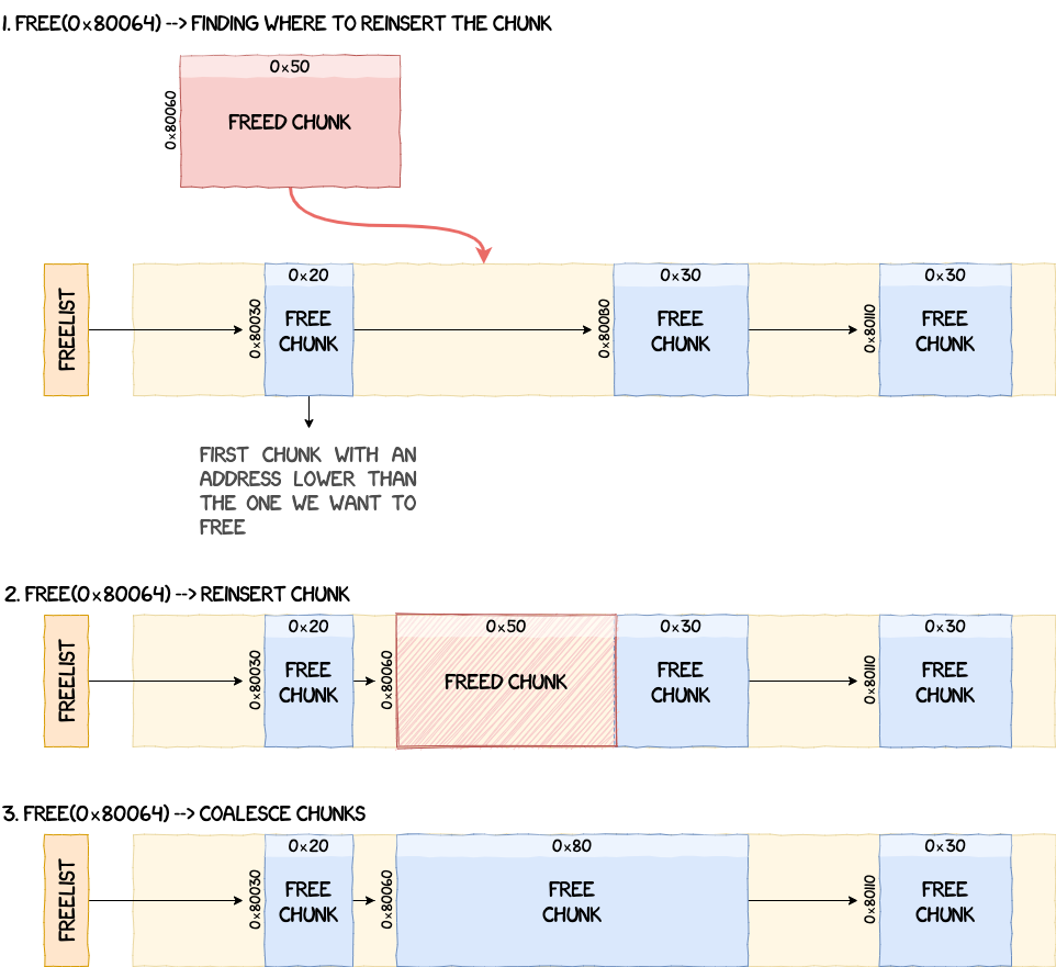
The opposite process is performed when the OS asks for memory to be freed. free iterates through the freelist and looks for the first chunk that has an address lower than the one we want to insert to keep the list sorted by chunk addresses. If two chunks are adjacent, they get coalesced.
Caches, Exceptions and Interrupts
After the initialization of the heap, the next function called is arm_init.
arm_init starts by initializing the CPU caches with a call to init_caches. It basically just retrieves some information about CPU caches and invalidates different memory regions to start from a clean state.
arm_init then initializes the exceptions in init_exception. The exception handlers referenced by the ARM exception vector table are only wrappers using function pointers to call the actual handlers. And, as you might have guessed, these function pointers are set in init_exception.
Finally, arm_init initializes the interrupts in init_interrupt. Basically, it configures the ARM Global Interrupt Controller and resets all pending interrupts. During the rest of the initialization process, the OS registers and enables multiple interrupt handlers using the function request_irq. Now, when an interrupt occurs, it goes through the relevant exception handler and reaches irq_fiq_handler. This function then calls handle_isr_func which retrieves the interrupt ID and calls the associated handler.
Note: There are a lot of details omitted regarding the interactions with ARM's GIC which can be found in the comments of the reversed functions.
Tasks
In this section, we deviate a bit from the initialization order of the main function. The reason is that all the components other than the heap are directly linked to tasks, which is why they are explained first.
NPU tasks are based on the following structure:
struct task {
    u32 magic;
    void *stack_ptr;
    void *stack_start;
    void *stack_end;
    u32 stack_size;
    u32 state;
    u32 unknown;
    u32 priority;
    void (*handler)(void *);
    u32 max_sched_slices;
    u32 total_sched_slices;
    u32 remaining_sched_slices;
    u32 delay;
    void *args;
    char *name;
    struct list_head tasks_list_entry;
    struct list_head ready_list_entry;
    struct list_head delayed_list_entry;
    struct list_head pending_list_entry;
    struct workqueue* wait_queue;
    char unknown2[60];
};
Note: All lists described in this article, apart from heap chunks, are doubly linked lists.
All tasks share the address space of the kernel, have their own dedicated stack and their execution time is managed by a scheduler (which is explained in the following section).
A task is created using the function create_task. It adds the task to the global task list and configures several properties such as:
- its name;
- its priority;
- the function it will run;
- its state (initially set to suspended);
- its stack's size, start and end address;
- various scheduling settings.
create_task also initializes the values written on the stack using init_task_stack. These values will be used when the task is scheduled by the OS to set the registers, the CPSR and resume the execution. The initial values are the following:
| Offset | Name | Value |
|---|---|---|
sp+0x00 |
r4 | 0 |
sp+0x04 |
r5 | 0 |
sp+0x08 |
r6 | 0 |
sp+0x0c |
r7 | 0 |
sp+0x10 |
r8 | 0 |
sp+0x14 |
r9 | 0 |
sp+0x18 |
r10 | 0 |
sp+0x1C |
r11 | 0 |
sp+0x20 |
r0 | 0 |
sp+0x24 |
r1 | 0 |
sp+0x28 |
r2 | 0 |
sp+0x2c |
r3 | 0 |
sp+0x30 |
r12 | 0 |
sp+0x34 |
lr | 0 |
sp+0x38 |
pc | run_task |
sp+0x3c |
cpsr | 0x153 |
When a task gets scheduled for the first time, its entry point is run_task. This function is a state machine that calls the task's handler, suspends it when its done and loops back again.
Once a task is running it's possible to resume or suspend it.
- Suspending a task is performed by calling
__suspend_task. Depending on the current state of the task (i.e. ready/running, sleeping, pending), it gets deleted from the list it's currently in (i.e. ready, delayed, pending) and its state set toTASK_SUSPENDED. The type of list a task can belong to is explained in the following section dedicated to the scheduler. - Resuming a task is performed by calling
__resume_task. This function simply adds the list to the ready list and sets its state toTASK_READY.
Scheduling
Like most operating systems, the NPU OS can handle multitasking and decides which task to run using a scheduler. The scheduler is initialized in the function scheduler_init and its state is tracked using the following structure:
struct scheduler_state_t {
    u32 scheduler_stopped;
    u32 forbid_scheduling;
    u8 prio_grp1[4];
    u8 prio_grp2[4][8];
    u8 prio_grp0;
    struct list_head tasks_list;
    struct list_head delayed_list;
    struct list_head ready_list[TASK_MAX_PRIORITY];
    u32 unknown;
    u32 nb_tasks;
    u32 count_sched_slices;
};
scheduler_init simply initializes the task lists, the priority group values and sets scheduler_stopped/forbid_scheduling to signify to the OS that it should not schedule tasks for the moment. But, before we can go any further, we need to explain what priority groups are, ready lists and, more generally, the scheduling algorithm.
Priority Groups
The scheduler implemented in the NPU is based on the priority associated with a task during its creation. For the NPU OS, a distinction should be made between the priority value of a task and its actual priority, since they are inverted: a high-priority task has a low priority value. Therefore finding the next task to schedule equates to finding the lowest priority task ready to run.
The lists of tasks ready to execute are stored in the scheduler's global state structure, with one ready list for each priority values (which goes from 0x00 to 0xff).
#define TASK_MAX_PRIORITY 0x100

struct scheduler_state_t {
    /* [...] */
    struct list_head ready_list[TASK_MAX_PRIORITY];
    /* [...] */
};
Now to be able to find the list in which the lowest priority task is, there are different solutions possible. A naive approach would be to iterate through all of these lists, find the first one that is non-empty and return the first task in it. The implementation used by Samsung is a bit different. To understand it, let's have a look at the function that adds a task into its ready list: __add_to_ready_list.
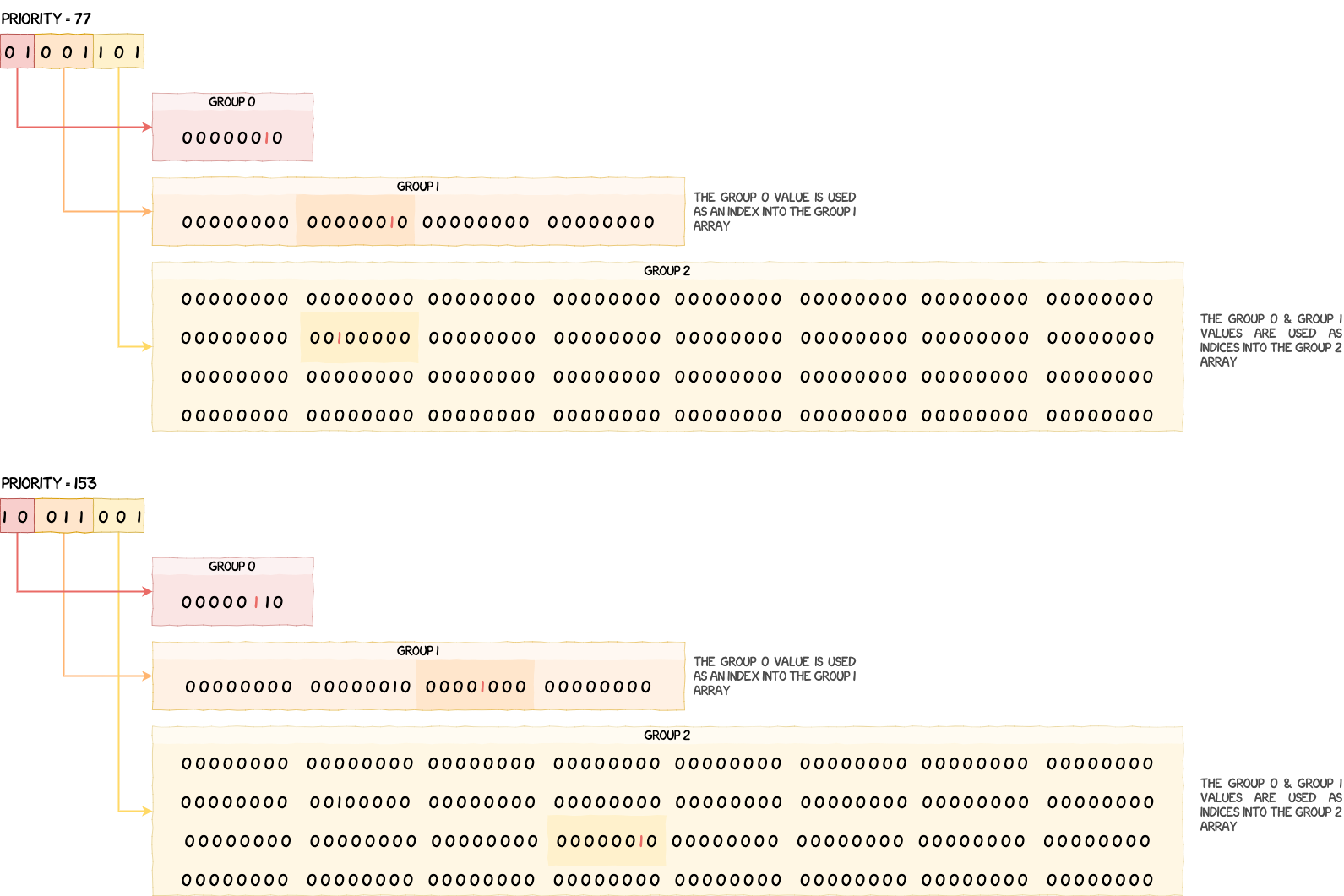
__add_to_ready_list takes the priority of the task we want to add into the ready list and splits it into three groups:
/* Computes the priority group values based on the task's priority */
u8 grp0_val = priority >> 6;
u8 grp1_val = (priority >> 3) & 7;
u8 grp2_val = priority & 7;
If we have a priority of 77, or 0b01001101 in binary, its value would be split as follows:
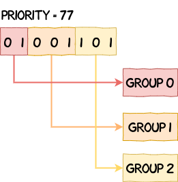
These values are then used to set bits in the three bitfields of g_scheduler_state.
/* Adds the current task's priority to the priority group values */
g_scheduler_state.prio_grp0 |= 1 << grp0_val;
g_scheduler_state.prio_grp1[grp0_val] |= 1 << grp1_val;
g_scheduler_state.prio_grp2[grp0_val][grp1_val] |= 1 << grp2_val;
Below is a visual representation of how these bitfields are modified when adding a task of priority 77 and then one of priority 153.
Now that it's clear how task priorities are referenced by the scheduler, let's detail the algorithm used to find the lowest priority encoded in these bitfields.
Scheduling Algorithm
To understand the algorithm, let's have a look at schedule_task. We can see that the values in the bitfields are retrieved and then used as indices into g_priority_table.
/* Finds the priority of the next task to schedule */
u32 prio_grp0_idx = g_scheduler_state.prio_grp0;
u32 prio_grp0_val = g_priority_table[prio_grp0_idx];
u32 prio_grp1_idx = g_scheduler_state.prio_grp1[prio_grp0_val];
u32 prio_grp1_val = g_priority_table[prio_grp1_idx];
u32 prio_grp2_idx = g_scheduler_state.prio_grp2[prio_grp0_val][prio_grp1_val];
u32 prio_grp2_val = g_priority_table[prio_grp2_idx];
The value we get back from this table, which is given below, is actually the index of the least significant set bit.
u8 g_priority_table[] = {
    0,0,1,0,2,0,1,0,3,0,1,0,2,0,1,0,
    4,0,1,0,2,0,1,0,3,0,1,0,2,0,1,0,
    5,0,1,0,2,0,1,0,3,0,1,0,2,0,1,0,
    4,0,1,0,2,0,1,0,3,0,1,0,2,0,1,0,
    6,0,1,0,2,0,1,0,3,0,1,0,2,0,1,0,
    4,0,1,0,2,0,1,0,3,0,1,0,2,0,1,0,
    5,0,1,0,2,0,1,0,3,0,1,0,2,0,1,0,
    4,0,1,0,2,0,1,0,3,0,1,0,2,0,1,0,
    7,0,1,0,2,0,1,0,3,0,1,0,2,0,1,0,
    4,0,1,0,2,0,1,0,3,0,1,0,2,0,1,0,
    5,0,1,0,2,0,1,0,3,0,1,0,2,0,1,0,
    4,0,1,0,2,0,1,0,3,0,1,0,2,0,1,0,
    6,0,1,0,2,0,1,0,3,0,1,0,2,0,1,0,
    4,0,1,0,2,0,1,0,3,0,1,0,2,0,1,0,
    5,0,1,0,2,0,1,0,3,0,1,0,2,0,1,0,
    4,0,1,0,2,0,1,0,3,0,1,0,2,0,1,0,
};
Assuming you have a value between 0x00 and 0x100, such as 0xc8 for example, the value you get back at this index is 3, because 0xc8 = 0b11001000 and the least significant bit set is at index 3. Since the position of a given bit in g_scheduler_state's bitfields is directly determined by the priority of a task, finding the least significant bit set allows us to extract and reconstruct the lowest priority value that can be scheduled.
Using this property, we are able to compute the priority of the next task to schedule, i.e. the one with the lowest priority value. Below is an example of this process with four tasks of priorities 54, 77, 153 and 252. We can see that after applying the algorithm, we get back the lowest priority value, which is 54 in this case.
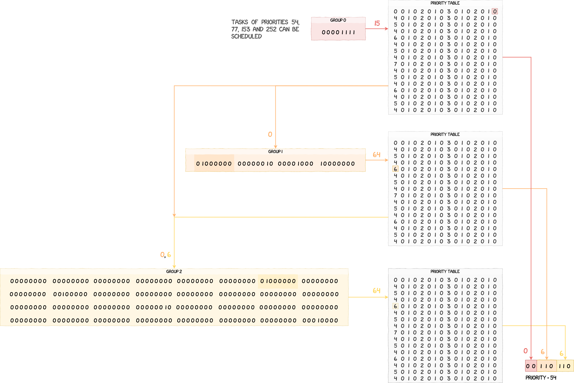
When the lowest priority value is found, schedule_task checks if it's lower than the priority of the currently running task, selects the corresponding ready list in g_scheduler_state.ready_list and runs the first task in that list.
Using the Scheduler
At this point, we have a good understanding of how the scheduler makes a decision. However, we still don't know what triggers the scheduler. The operating systems we are generally most familiar with use preemption to stop a task that has been running for too long. This is not the case for the NPU; as far as we know, there is no preemption and tasks have to yield the CPU explicitly for other tasks to run. This can be done in multiple ways, e.g. by making the process sleep, wait for an event, etc., however it requires the task in question to explicitly call these functions at some point, otherwise they would monopolize CPU time.
All the operations listed above call, at some point, the function schedule. It is responsible for saving the context of the current task, call schedule_task (which was explained in the previous section) and, if the task to schedule is different from the current one, do a context switch.
The only parts of the scheduler left to explain are the different lists used to manage tasks.
Ready List
As explained previously, ready lists are an array of lists indexed by the priority of the tasks they hold. It's possible to add and remove a task from a ready list using __add_to_ready_list and __del_from_ready_list. In a nutshell, these functions update the priority groups from g_scheduler_state and add or remove the task from the g_scheduler_state.ready_list entry that corresponds to the priority of the task. They are simply an extension of the algorithm explained in the previous section.
Delayed List
On other operating systems, it is possible to make a process sleep for a given duration. This is what delayed lists in the NPU are for. To manage the passing of time and know when to wake up a task, the handler for the timer IRQ, that happens every timer tick, calls schedule_tick which decrements tasks' delay by one. Timer ticks, and also scheduler time-slices, are 1ms long.
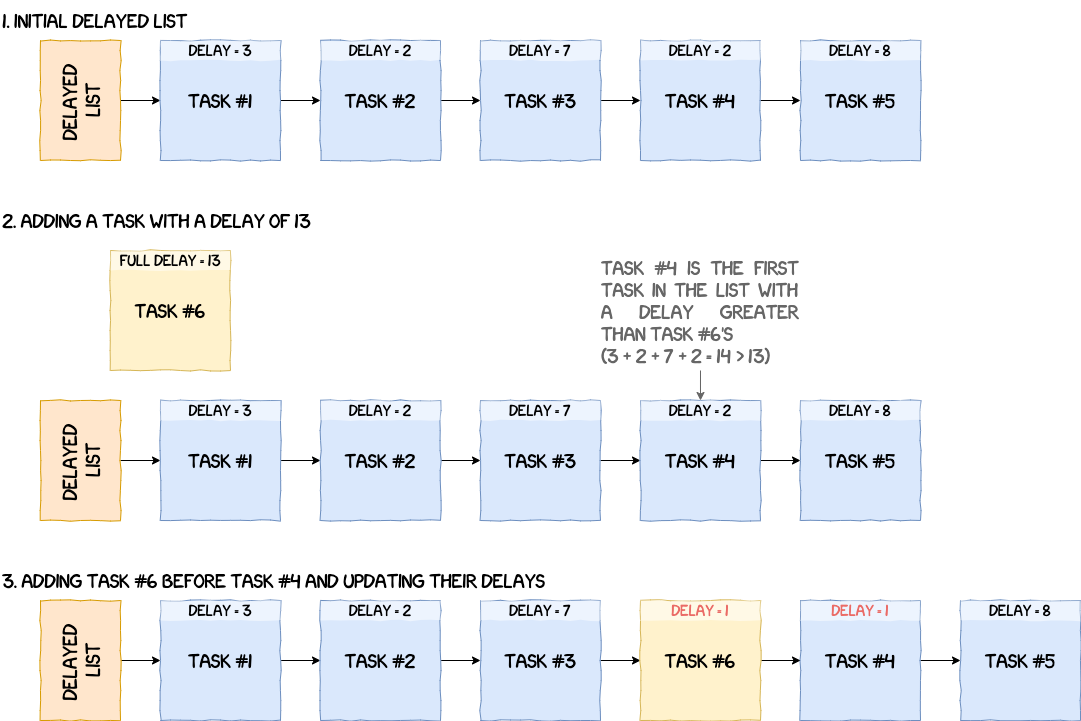
A task can be delayed using the function __add_to_delayed_list. The idea is to add the task to g_scheduler_state.delayed_list, but it needs to be sorted by delay first. An important thing to note, is that tasks' delay in the delayed list are relative to each other. For example, if a task A is delayed for three timer ticks and a task B for five timer ticks, then A is added to the list with a delay of three, but B is added with a delay of two (since 3 + 2 = 5). The figure below illustrates the process of adding a task to the delayed list.
Removing a task from the delayed list can be done in two ways.
- The first one is an explicit call to
__del_from_delayed_listand does not wait for the delay to finish on its own. It takes the task we want to wake up, adds its delay to the next one and removes it from the list. - The second method is waiting for the delay to reach zero. Every time
schedule_tickis called, it decrements the delay of the first task in the delayed list by one, but it also checks if one or more tasks has reached a delay of zero (or less) to wake them up.
Pending List
The pending list is used to reference tasks waiting for a specific event to occur (e.g. a lock waiting to be released).
Contrary to ready and delayed lists, pending lists are not part of the g_scheduler_state, but of a workqueue defined by the following structure:
struct workqueue {
    u32 task;
    struct list_head head;
    u32 service;
    void* obj;
};
workqueue-s are associated with a specific object (semaphore or event) and, when a task is waiting for an action from one of these objects, it gets added to the pending list struct list_head head. This operation is performed by functions that ultimately call __add_to_pending_list. In a pending list, tasks can be sorted by priority, but it depends on the value of the field service (0 = no sorting, 1 = sorting by priority). Removing a task can be done using __del_from_pending_list which basically just unlinks the task from the pending list in question.
We will give a bit more details on how this list is used in the sections on semaphores and events.
Timers
Everything related to time originates from the function timer_irq_handler which is called every 1ms.
void timer_irq_handler() {
    time_tick();
    if ( !g_scheduler_state.scheduler_stopped )
        schedule_tick();
}
time_tick increments the global ticks counter (which is used in debug messages for example), but also handles timers. Timers can potentially be used by the NPU to execute functions at regular intervals and/or at a given time. However, it doesn't seem to be the case with this version of the NPU, so we'll keep this section short and skip to the next part.
Events
Because the NPU interacts with other components and, to some extent, the user of the device, exchanges are inherently asynchronous. There needs to be a mechanism able to manage these types of communications.
To handle this, the NPU uses objects called events, which are defined by the following structure:
struct event {
    u32 magic;
    u32 id;
    u32 _unk_0c;
    u32 state;
    struct list_head event_list_entry;
    struct list_head waiting_list_entry;
    struct workqueue wq;
};
As we will see later, events are used to make a function wait for a specific event. For example, we don't know when a new message is sent to a mailbox. So instead of waiting actively in a loop, the OS makes the task sleep, adds it to a waiting list and, when the event actually occurs, takes it out of the waiting list to handle the incoming message.
Events are initialized in the function events_init, which configures the number of active events, pending and event lists, counts and event objects (which are directly stored in the global state g_events_state).
Creating a new event is made through a call to __alloc_event. The function looks for an empty spot in the g_events_state.events array and then:
- sets its ID (with a value passed as argument);
- sets its state to
EVENT_READY; - adds it to the global event list
g_events_state.event_list; - updates
g_events_state's counts, flags, etc.; - initializes the event's workqueue.
The freeing process is simply the opposite of __alloc_event and is implemented in __free_event. It deinitializes the workqueue and resets the event in g_events_state.
Regarding the usage of events, there are two functions implemented.
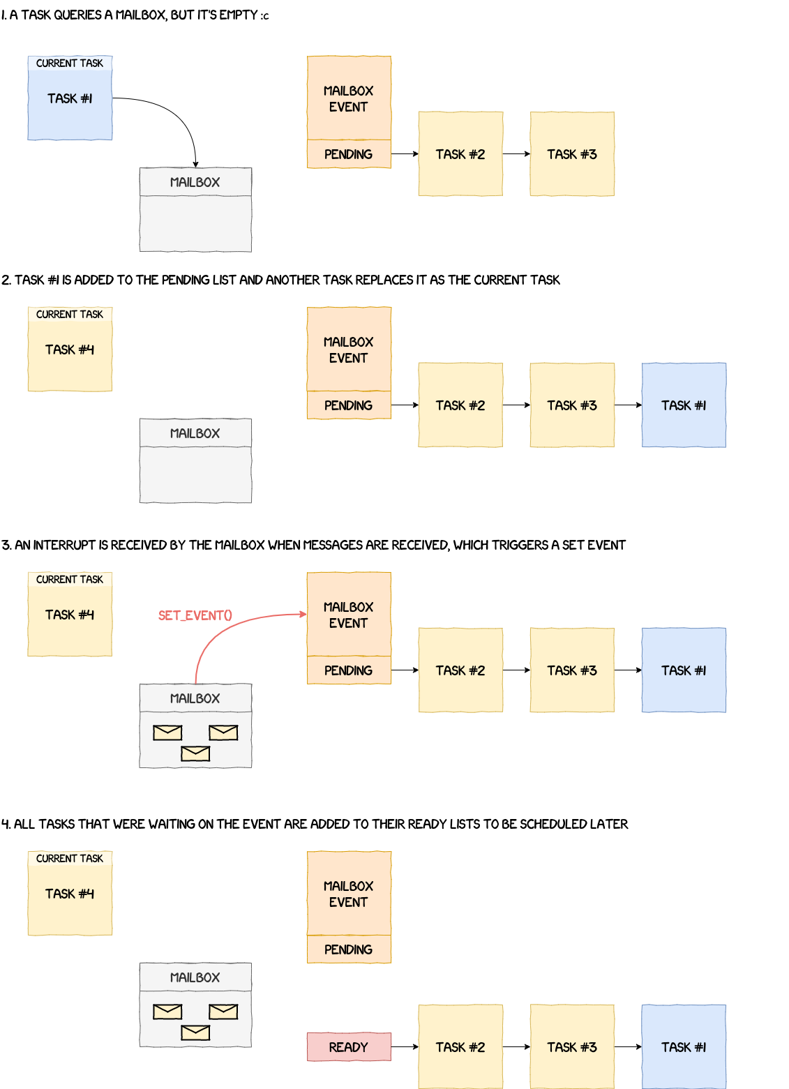
__wait_event, as its name suggests, makes a task wait for a specific event to occur. This function simply takes the task currently running, removes it from the ready list and adds it to the pending list of the event's workqueue. Additionally, if it has not already been done, the event is added to the waiting list of the corresponding ID (i.e.struct list_head event_waiting_lists[MAX_EVENT_IDS + 1]). There can be multiple events using the same ID and, therefore, in the same waiting list.- The function used to signify that an event occurred is
__set_event_no_schedule. It seems a bit more complex, but it's not really the case because most of the code is duplicated. The general idea is that the function takes the ID from the event and retrieves the waiting list associated with it ing_events_state. It then goes through each event from the waiting list and tries to wake up all tasks waiting on these events.
A simplified representation of this wait/set process is given in the figure below.
Semaphores
Semaphores are used in operating systems to control the access to shared resources and to prevent issues such as race conditions. A count is associated with them and every time a task takes a semaphore, its count is reduced by one. When the count is zero, the next task that tries to take the semaphore has to wait for another task to give back theirs.
In the NPU, the global structure g_semaphores_state used by semaphores is defined by the following structure:
struct semaphores_state_t {
    u32 nb_semaphores;
    struct list_head semaphore_list;
};
semaphores_init simply initializes the semaphore counts and the semaphore list. At this point, it's possible to create a new semaphore using __create_semaphore. It initializes its workqueue, its count, its name and then adds it to the global semaphore list. Conversely, a semaphore is deleted using __delete_semaphore, which deinitializes and cleans up the workqueue as well as the rest of the semaphore parameters.
The behavior of a semaphore is pretty similar to that of an event. When taking a semaphore using __down, it simply decrements the count by one each call. But when the count is less than zero, it removes the current task from the ready list, adds it to the pending list of the semaphore's workqueue and schedules a new task. Giving back a semaphore with __up works in a similar manner. If the semaphore's workqueue is empty, it means no tasks are waiting on the semaphore, so we can simply increment the count by one. However, if the list is not empty, then the task waiting needs to be woken up and added back to the ready list using __up_sema_no_schedule.
Communication Channels
This section deals with the initialization of the communication channels between the NPU and the AP (i.e. the application processor running Android). However, some functions related to this part are either irrelevant, unused or we're simply not sure what they do. Thankfully, they're not too important for the overall understanding of what's going on.
The configuration takes place in the function comm_channels_init. It starts with the initialization of the mailbox with a call to mailbox_init. This function allocates the events and sets up the interrupt handlers to notify the system of incoming messages in the high and low priority mailboxes. The next step is to call cmdq_init which configures the CMDQ (Command Queue?) subsystem by performing similar operations than mailbox_init.
The rest of comm_channels_init initializes other components, but we were not able to figure out what they do exactly or how they are used by the rest of the system.
Running the System
We're finally reaching the end of the initialization process. The last thing left to do, before effectively starting the system, is to configure the core tasks handling all interactions between the AP and the NPU. These tasks, in the context of the NPU, are called native tasks and are based on the following structure:
struct native_task {
    u32 unknown[0xc];
    u32 id;
    char name[8];
    u32 priority;
    u32 handler;
    u32 max_sched_slices;
    u32 stack_addr;
    u32 stack_size;
    struct task task;
    u32 unknown;
};
Native tasks are set up in the function run_native_tasks and there are eleven of them. Below is a table that summarizes most of this information.
| ID | Name | Priority | Sched Slices | Stack Base | Stack Size |
|---|---|---|---|---|---|
0x00 |
__MON | 0x00 |
0x64 |
0x37800 |
0x400 |
0x01 |
_IDLE | 0xff |
0x64 |
0x37c00 |
0x200 |
0x02 |
__LOW | 0x14 |
0x64 |
0x37e00 |
0x800 |
0x03 |
_HIGH | 0x0a |
0x64 |
0x38600 |
0x400 |
0x04 |
_RSPS | 0x09 |
0x64 |
0x38a00 |
0x400 |
0x05 |
__RPT | 0x14 |
0x64 |
0x38e00 |
0x400 |
0x06 |
__IMM | 0x0e |
0x64 |
0x39200 |
0x800 |
0x07 |
__BAT | 0x0f |
0x64 |
0x39a00 |
0x800 |
0x08 |
JOBQ0 | 0x15 |
0x64 |
0x3a200 |
0x1000 |
0x09 |
JOBQ1 | 0x16 |
0x64 |
0x3b200 |
0x200 |
0x0A |
JOBQ2 | 0x17 |
0x64 |
0x3b400 |
0x200 |
For each native task structure, a call to create_task is made to effectively instantiate the associated tasks. resume_task then adds them to their respective ready lists before the final call to schedule_start.
The function schedule_start:
- Finds the lowest priority value encoded in the priority groups (in this case 0);
- Sets
g_scheduler_state.scheduler_stoppedandg_scheduler_state.forbid_schedulingto 0, to signify to the OS that scheduling is now possible; - Makes a context switch to the highest priority task (in this case, the monitor).
We won't detail all of the native tasks in this article, but simply give a brief description to get a general idea of what they do.
- Monitor: initializes the intrinsic lib used for neural computations, the IOE dispatcher (?), the NCP manager that handles objects sent by the AP and finally the mailboxes. It also checks every second that a task has not timed out.
- Idle Task: does nothing and is just used to fill in until another task is ready to run.
- High & Low Priority Mailboxes: receive and handle requests from the AP.
- Response Task: answers the AP.
- Report Task: sends logs to the AP.
- Imm & Bat Dispatchers: unfortunately we didn't take time to look at these and therefore don't know what they do.
- Job Queues: only print a debug message and return.
In the next section, we give more details on the mailbox implementations and explain how we can interact with the NPU from the AP.
Interacting with the NPU
As we've seen in the previous sections, it's possible to send messages to the NPU using its mailboxes. However, we've not explained their implementations yet. Since, communication channels also have a part implemented in the Android kernel, we'll detail the steps taken by a request from the moment an ioctl is made up to the reception of a response from the NPU by the kernel.
Sharing Resources Between the Kernel and the NPU
Before we can talk about communication between the NPU and the AP, we need to explain how they are able to exchange data and, more specifically, how memory sharing works between these two chips.
We've already introduced earlier the function init_iomem_area which is responsible for performing this mapping. It parses the file arch/arm64/boot/dts/exynos/exynos9830.dts and, more specifically, the part given below.
npu_exynos {
    ...
    samsung,npumem-address = <0x00 0x17800000 0x100000 0x00 0x17900000 0x100000 0x00 0x17a00000 0x100000 0x00 0x17b00000 0x40000 0x00 0x17c00000 0x100000 0x00 0x17d00000 0x100000 0x00 0x17e00000 0x100000 0x00 0x17f00000 0x100000 0x00 0x1e00c000 0x1000 0x00 0x1e00b000 0x1000 0x00 0x10040100 0x08 0x00 0x106f0000 0x1000 0x00 0x179c0000 0x10000 0x00 0x17ac0000 0x10000 0x00 0x19400000 0x200000 0x00 0x50000000 0xe0000 0x00 0x50100000 0x200000 0x00 0x50300000 0x200000>;
    samsung,npumem-names = "SFR_DNC\0SFR_NPUC0\0SFR_NPUC1\0TCUSRAM\0SFR_NPU0\0SFR_NPU1\0SFR_NPU2\0SFR_NPU3\0SFR_CORESIGHT\0SFR_STM\0SFR_MCT_G\0PWM\0MAILBOX0\0MAILBOX1\0IDPSRAM\0FW_DRAM\0FW_UNITTEST\0FW_LOG";
    ...
};
It extracts the memory region names from samsung,npumem-names as well as the corresponding mappings in samsung,npumem-address. The mappings are encoded following the structure given below:
struct iomem_reg_t {
    u32 dummy;
    u32 start;
    u32 size;
};
Using the values from the file above, we get the following mappings:
| Name | Dummy | Start | Size |
|---|---|---|---|
| SFR_DNC | 0x00 | 0x17800000 | 0x100000 |
| SFR_NPUC0 | 0x00 | 0x17900000 | 0x100000 |
| SFR_NPUC1 | 0x00 | 0x17a00000 | 0x100000 |
| TCUSRAM | 0x00 | 0x17b00000 | 0x40000 |
| SFR_NPU0 | 0x00 | 0x17c00000 | 0x100000 |
| SFR_NPU1 | 0x00 | 0x17d00000 | 0x100000 |
| SFR_NPU2 | 0x00 | 0x17e00000 | 0x100000 |
| SFR_NPU3 | 0x00 | 0x17f00000 | 0x100000 |
| SFR_CORESIGHT | 0x00 | 0x1e00c000 | 0x1000 |
| SFR_STM | 0x00 | 0x1e00b000 | 0x1000 |
| SFR_MCT_G | 0x00 | 0x10040100 | 0x08 |
| PWM | 0x00 | 0x106f0000 | 0x1000 |
| MAILBOX0 | 0x00 | 0x179c0000 | 0x10000 |
| MAILBOX1 | 0x00 | 0x17ac0000 | 0x10000 |
| IDPSRAM | 0x00 | 0x19400000 | 0x200000 |
| FW_DRAM | 0x00 | 0x50000000 | 0xe0000 |
| FW_UNITTEST | 0x00 | 0x50100000 | 0x200000 |
| FW_LOG | 0x00 | 0x50300000 | 0x200000 |
The one we're interested in here is FW_DRAM. It maps the NPU firmware in the first 0x80000 bytes and shared data in the remaining 0x60000. When init_iomem_area iterates over the different mappings, once it reaches FW_DRAM, it calls the function npu_memory_alloc_from_heap to create a shared memory mapping between the kernel and the NPU.
static int init_iomem_area(struct npu_system *system)
{
    /* [...] */
    iomem_count = of_property_count_strings(
            dev->of_node, "samsung,npumem-names");
    /* [...] */
    for (i = 0; i < iomem_count; i++) {
        ret = of_property_read_string_index(dev->of_node,
                "samsung,npumem-names", i, &iomem_name[i]);
        /* [...] */
    }
    /* [...] */
    ret = of_property_read_u32_array(dev->of_node, "samsung,npumem-address", (u32 *)iomem_data,
            iomem_count * sizeof(struct iomem_reg_t) / sizeof(u32));
    /* [...] */
    for (i = 0; iomem_name[i] != NULL; i++) {
        /* [...] */
        if (init_data[di].heapname) {
            /* [...] */
            ret = npu_memory_alloc_from_heap(system->pdev, *bd,
                    (iomem_data + i)->start, init_data[di].heapname);
            /* [...] */
        }
        /* [...] */
    }
    /* [...] */
}
npu_memory_alloc_from_heap then gets the IOMMU domain associated to the device before calling iommu_map.
static int npu_memory_alloc_from_heap(struct platform_device *pdev, struct npu_memory_buffer *buffer, dma_addr_t daddr, phys_addr_t paddr, const char *heapname)
{
        /* [...] */
        struct iommu_domain *domain = iommu_get_domain_for_dev(&pdev->dev);
        ret = iommu_map(domain, daddr, paddr, size, 0);
        if (ret) {
            npu_err("fail(err %pad) in iommu_map\n", &daddr);
            ret = -ENOMEM;
            goto p_err;
        }
        /* [...] */
}
iommu_map finally calls domain->ops->map which effectively maps the memory region between the NPU and the AP through the IOMMU.
int iommu_map(struct iommu_domain *domain, unsigned long iova,
          phys_addr_t paddr, size_t size, int prot)
{
        /* [...] */
        ret = domain->ops->map(domain, iova, paddr, pgsize, prot);
        /* [...] */
}
However, you might want to know what the domain is and the operations associated with it, and for this we have to dig a little bit deeper. The path from the initialization of the NPU device to the moment the domain is set is the following:
npu_device_initplatform_driver_register(usingplatform_bus_type)__platform_driver_registerdriver_registerbus_add_driverdriver_attach__driver_attachdriver_probe_devicereally_probedma_configure(using.dma_configurefromplatform_bus_type)platform_dma_configureof_dma_configureof_iommu_configureof_iommu_xlate(using.of_xlatefromexynos_iommu_ops)exynos_iommu_of_xlate
exynos_iommu_of_xlate finds the domain associated with the driver based on a list of clients.
static int exynos_iommu_of_xlate(struct device *master,
                 struct of_phandle_args *spec)
{
    /* [...] */
    if (!owner) {
        /* [...] */
        list_for_each_entry_safe(client, buf_client,
                    &exynos_client_list, list) {
            if (client->master_np == master->of_node) {
                domain = client->vmm_data->domain;
                vmm_data = client->vmm_data;
                list_del(&client->list);
                kfree(client);
                break;
            }
        }
        /* [...] */
        owner->domain = domain;
        owner->vmm_data = vmm_data;
        owner->master = master;
        /* [...] */
    }
    /* [...] */
}
The clients of an IOMMU domain are defined in the device tree file in the field domain-clients. They reference the phandle of the components that are associated with this domain. For example, in iommu-domain_dnc, the clients are 0x162and 0x163.
iommu-domain_dnc {
    compatible = "samsung,exynos-iommu-bus";
    #dma-address-cells = <0x01>;
    #dma-size-cells = <0x01>;
    dma-window = <0x80000000 0x50000000>;
    domain-clients = <0x162 0x163>;
};
0x163 corresponds to the phandle of the NPU.
npu_exynos {
    ...
    phandle = <0x163>;
};
These values are parsed in the function exynos_iommu_create_domain which also calls exynos_create_single_iovmm.
static int __init exynos_iommu_create_domain(void)
{
    struct device_node *domain_np;
    int ret;

    for_each_compatible_node(domain_np, NULL, "samsung,exynos-iommu-bus") {
        /* [...] */
        ret = of_get_dma_window(domain_np, NULL, 0, NULL, &d_addr, &d_size);
        if (!ret) {
            /* [...] */
            start = d_addr;
            end = d_addr + d_size;
        }
        /* [...] */
        while ((np = of_parse_phandle(domain_np, "domain-clients", i++))) {
            if (!vmm) {
                vmm = exynos_create_single_iovmm(np->name,
                                start, end);
                /* [...] */
                /* HACK: Make one group for one domain */
                domain = to_exynos_domain(vmm->domain);
                vmm->group = iommu_group_alloc();
                iommu_attach_group(vmm->domain, vmm->group);
            }
            /* Relationship between domain and client is added. */
            ret = exynos_client_add(np, vmm);
            /* [...] */
        }
        /* [...] */
    }

    return 0;
}
exynos_create_single_iovmm then calls iommu_domain_alloc which is a wrapper for __iommu_domain_alloc.
struct exynos_iovmm *exynos_create_single_iovmm(const char *name,
                    unsigned int start, unsigned int end)
{
    /* [...] */
    vmm->domain = iommu_domain_alloc(&platform_bus_type);
}
struct iommu_domain *iommu_domain_alloc(struct bus_type *bus)
{
    return __iommu_domain_alloc(bus, IOMMU_DOMAIN_UNMANAGED);
}
Finally, in __iommu_domain_alloc, domain->ops is set to platform_bus_type.iommu_ops.
static struct iommu_domain *__iommu_domain_alloc(struct bus_type *bus,
                         unsigned type)
{
    /* [...] */
    domain->ops  = bus->iommu_ops;
    /* [...] */
}
iommu_ops is set exynos_iommu_init with a call to bus_set_iommu.
static int __init exynos_iommu_init(void)
{
    /* [...] */
    ret = bus_set_iommu(&platform_bus_type, &exynos_iommu_ops);
    /* [...] */
}
static struct iommu_ops exynos_iommu_ops = {
    .domain_alloc = exynos_iommu_domain_alloc,
    .domain_free = exynos_iommu_domain_free,
    .attach_dev = exynos_iommu_attach_device,
    .detach_dev = exynos_iommu_detach_device,
    .map = exynos_iommu_map,
    .unmap = exynos_iommu_unmap,
    .iova_to_phys = exynos_iommu_iova_to_phys,
    .pgsize_bitmap = SECT_SIZE | LPAGE_SIZE | SPAGE_SIZE,
    .of_xlate = exynos_iommu_of_xlate,
};
After all this, we know that when domain->ops->map is called in iommu_map, it's exynos_iommu_map that is actually executed.
int iommu_map(struct iommu_domain *domain, unsigned long iova,
          phys_addr_t paddr, size_t size, int prot)
{
        /* [...] */
        ret = domain->ops->map(domain, iova, paddr, pgsize, prot);
        /* [...] */
}
Now that our shared memory mapping has been created, we can start analyzing the path taken by a request originating from the kernel and sent to the NPU.
From the Kernel to the NPU
To illustrate the path taken by a request sent from a user, we will take the ioctl VS4L_VERTEXIOC_S_FORMAT as an example.
Ioctl handling starts in the function vertex_ioctl and reaches, in our example, the case VS4L_VERTEXIOC_S_FORMAT.
long vertex_ioctl(struct file *file, unsigned int cmd, unsigned long arg)
{
    /* [...] */
    int ret = 0;
    struct vision_device *vdev = vision_devdata(file);
    const struct vertex_ioctl_ops *ops = vdev->ioctl_ops;

    /* temp var to support each ioctl */
    union {
        /* [...] */
        struct vs4l_format_list vsf;
        /* [...] */
    } vs4l_kvar;

    /* [...] */
    switch (cmd) {
    /* [...] */
    case VS4L_VERTEXIOC_S_FORMAT:
        ret = get_vs4l_format64(&vs4l_kvar.vsf,
                (struct vs4l_format_list __user *)arg);
        if (ret) {
            vision_err("get_vs4l_format64 (%d)\n", ret);
            break;
        }

        ret = ops->vertexioc_s_format(file, &vs4l_kvar.vsf);
        if (ret)
            vision_err("vertexioc_s_format (%d)\n", ret);

        put_vs4l_format64(&vs4l_kvar.vsf,
                (struct vs4l_format_list __user *)arg);
        break;
    /* [...] */
get_vs4l_format64 simply retrieves the structure from userspace and checks that values are sane. The execution flow is then handed over to ops->vertexioc_s_format, which corresponds to the function npu_vertex_s_format.
npu_vertex_s_format then calls npu_session_NW_CMD_LOAD when sending an outgoing request.
static int npu_vertex_s_format(struct file *file, struct vs4l_format_list *flist)
{
    /* [...] */
    if (flist->direction == VS4L_DIRECTION_OT) {
        ret = npu_session_NW_CMD_LOAD(session);
        ret = chk_nw_result_no_error(session);
        if (ret == NPU_ERR_NO_ERROR) {
            vctx->state |= BIT(NPU_VERTEX_FORMAT);
        } else {
            goto p_err;
        }
    }
    /* [...] */
}
npu_session_NW_CMD_LOAD passes the current session and command to npu_session_put_nw_req.
int npu_session_NW_CMD_LOAD(struct npu_session *session)
{
    int ret = 0;
    nw_cmd_e nw_cmd = NPU_NW_CMD_LOAD;

    if (!session) {
        npu_err("invalid session\n");
        ret = -EINVAL;
        return ret;
    }

    profile_point1(PROBE_ID_DD_NW_RECEIVED, session->uid, 0, nw_cmd);
    session->nw_result.result_code = NPU_NW_JUST_STARTED;
    npu_session_put_nw_req(session, nw_cmd);
    wait_event(session->wq, session->nw_result.result_code != NPU_NW_JUST_STARTED);
    profile_point1(PROBE_ID_DD_NW_NOTIFIED, session->uid, 0, nw_cmd);
    return ret;
}
npu_session_put_nw_req fills the request object and passes it to npu_ncp_mgmt_put.
static int npu_session_put_nw_req(struct npu_session *session, nw_cmd_e nw_cmd)
{
    int ret = 0;
    struct npu_nw req = {
        .uid = session->uid,
        .bound_id = session->sched_param.bound_id,
        .npu_req_id = 0,
        .result_code = 0,
        .session = session,
        .cmd = nw_cmd,
        .ncp_addr = session->ncp_info.ncp_addr,
        .magic_tail = NPU_NW_MAGIC_TAIL,
    };

    BUG_ON(!session);

    req.notify_func = get_notify_func(nw_cmd);

    ret = npu_ncp_mgmt_put(&req);
    if (!ret) {
        npu_uerr("npu_ncp_mgmt_put failed", session);
        return ret;
    }
    return ret;
}
npu_ncp_mgmt_put pushes the request in the FREE fifo list.
int npu_ncp_mgmt_put(const struct npu_nw *frame)
{
    int ret;

    BUG_ON(!frame);
    ret = kfifo_in_spinlocked(&ctx.ncp_mgmt_list, frame, 1, &ctx.ncp_mgmt_lock);
    if (ret > 0) {
        if (ctx.ncp_mgmt_callback)  {
            ctx.ncp_mgmt_callback();
        }
    }
    return ret;
}
npu_protodrv_handler_nw_free retrieves this request and pushes it into the REQUESTED list.
static int npu_protodrv_handler_nw_free(void)
{
    /* [...] */

    /* Take a entry from FREE list, before access the queue */
    while ((entry = proto_nw_lsm.lsm_get_entry(FREE)) != NULL) {
        /* Is request available ? */
        if (nw_mgmt_op_get_request(entry) != 0) {
            /* [...] */
            /* Move to REQUESTED state */
            proto_nw_lsm.lsm_put_entry(REQUESTED, entry);
            handle_cnt++;
            goto finally;
            /* [...] */
npu_protodrv_handler_nw_requested retrieves the request and passes it to __mbox_nw_ops_put.
static int npu_protodrv_handler_nw_requested(void)
{
    /* [...] */
    /* Process each element in REQUESTED list one by one */
    LSM_FOR_EACH_ENTRY_IN(proto_nw_lsm, REQUESTED, entry,
        /* [...] */
        switch (entry->nw.cmd) {
        /* [...] */
        default:
            /* Conventional command -> Publish message to mailbox */
            if (__mbox_nw_ops_put(entry) > 0) {
                /* Success */
                proto_nw_lsm.lsm_move_entry(PROCESSING, entry);
                proc_handle_cnt++;
            }
            break;
        }
    ) /* End of LSM_FOR_EACH_ENTRY_IN */
    /* [...] */
}
__mbox_nw_ops_put is simply a wrapper for nw_mbox_ops_put, which calls npu_nw_mbox_ops_put.
static int __mbox_nw_ops_put(struct proto_req_nw *entry)
{
    /* [...] */
    ret = nw_mbox_ops_put(entry);
    /* [...] */
}
static int nw_mbox_ops_put(struct proto_req_nw *src)
{
    return npu_nw_mbox_ops_put(&npu_proto_drv.msgid_pool, src);
}
npu_nw_mbox_ops_put then calls npu_if_protodrv_mbox_ops.nw_post_request on the request, which resolves to nw_req_manager.
int npu_nw_mbox_ops_put(struct msgid_pool *pool, struct proto_req_nw *src)
{
    /* [...] */
    /* Generate mailbox message with given msgid and post it */
    if (npu_if_protodrv_mbox_ops.nw_post_request)
        ret = npu_if_protodrv_mbox_ops.nw_post_request(msgid, &src->nw);
    /* [...] */
}
struct npu_if_protodrv_mbox_ops npu_if_protodrv_mbox_ops = {
    /* [...] */
    .nw_post_request = nw_req_manager,
    /* [...] */
};
nw_req_manager formats our message and passes it to npu_set_cmd. Notice that the request is meant to be sent in the low priority mailbox using the flag NPU_MBOX_REQUEST_LOW.
int nw_req_manager(int msgid, struct npu_nw *nw)
{
    /* [...] */
    switch (nw->cmd) {
    /* [...] */
    case NPU_NW_CMD_LOAD:
        cmd.c.load.oid = nw->uid;
        cmd.c.load.tid = nw->bound_id;
        hdr_size = get_ncp_hdr_size(nw);
        if (hdr_size <= 0) {
            npu_info("fail in get_ncp_hdr_size: (%zd)", hdr_size);
            ret = FALSE;
            goto nw_req_err;
        }

        cmd.length = (u32)hdr_size;
        cmd.payload = nw->ncp_addr.daddr;
        msg.command = COMMAND_LOAD;
        msg.length = sizeof(struct command);
        break;
    /* [...] */
    }
    msg.mid = msgid;

    ret = npu_set_cmd(&msg, &cmd, NPU_MBOX_REQUEST_LOW);
    if (ret)
        goto nw_req_err;
    /* [...] */
}
Finally, npu_set_cmd calls mbx_ipc_put which writes our message into shared memory and sends the interrupt to signify that a new message has been sent.
static int npu_set_cmd(struct message *msg, struct command *cmd, u32 cmdType)
{
    int ret = 0;

    ret = mbx_ipc_put((void *)interface.addr, &interface.mbox_hdr->h2fctrl[cmdType], msg, cmd);
    if (ret)
        goto I_ERR;
    __send_interrupt(msg->command);
    return 0
I_ERR:
    switch (ret) {
    case -ERESOURCE:
        npu_warn("No space left on mailbox : ret = %d\n", ret);
        break;
    default:
        npu_err("mbx_ipc_put err with %d\n", ret);
        break;
    }
    return ret;
}
Handling Commands in the NPU
At this stage in the execution, we know that a message is waiting in the low priority mailbox and that an interrupt was sent to the NPU. In this section, we give a quick rundown of the mailbox controls, which are used by the NPU and the AP to communicate the position of their read/write cursors in the shared ring buffer. Then we detail how the request is received, parsed and handled by the NPU. And, finally, we explain how the response is sent back to the kernel.
Mailbox Controls
The implementation of the mailbox used by the NPU is divided into five segments. One is the header of the mailbox and the other four are ring buffers used by:
- the low priority mailbox;
- the high priority mailbox;
- the response mailbox;
- the report mailbox.
Its layout looks as follows:
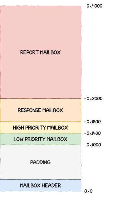
The mailbox header is defined using the structure struct mailbox_hdr below and is used to keep track of the different read/write pointers into the ring buffers.
struct mailbox_hdr {
    u32 max_slot;
    u32 debug_time;
    u32 debug_code;
    u32 log_level;
    u32 log_dram;
    u32 reserved[8];
    struct mailbox_ctrl h2fctrl[MAILBOX_H2FCTRL_MAX];
    struct mailbox_ctrl f2hctrl[MAILBOX_F2HCTRL_MAX];
    u32 totsize;
    u32 version;
    u32 signature2;
    u32 signature1;
};
The four mailbox controllers used by the NPU are initialized by the monitor with a call to the function mailbox_controller_init.
mailbox_controller_init first calls init_ncp_handlers to initialize the handlers for the commands sent by the AP.
u32 mailbox_controller_init() {
    /* [...] */

    /* Initializes the NCP handlers used for neural computation */
    init_ncp_handlers(&g_ncp_handler_state);

    /* [...] */
}
These handlers are set in the NCP handler global state structure g_ncp_handler_state.
void init_ncp_handlers(struct ncp_handler_state_t *ncp_handler_state) {
    ncp_handler_state->_unk_0x364 = 4;

    /* Sets all messages as unused */
    for (int i = 0; i < NB_MESSAGES; i++) {
        ncp_handler_state->messages[i].inuse = 0;
    }

    /* Initializes the handlers for the request commands */
    ncp_handler_state->handlers[0] = ncp_manager_load;
    ncp_handler_state->handlers[1] = ncp_manager_unload;
    ncp_handler_state->handlers[2] = ncp_manager_process;
    ncp_handler_state->handlers[3] = profile_control;
    ncp_handler_state->handlers[4] = ncp_manager_purge;
    ncp_handler_state->handlers[5] = ncp_manager_powerdown;
    ncp_handler_state->handlers[7] = ncp_manager_policy;
    ncp_handler_state->handlers[6] = ut_main_func;
    ncp_handler_state->handlers[8] = ncp_manager_end;
}
mailbox_controller_init then calls mbx_dnward_init twice for the high and low priority mailboxes, mbx_upward_init for the response mailbox and mbx_report_init for the reporting mailbox.
u32 mailbox_controller_init() {
    /* [...] */

    /* Initializes the low priority mailbox */
    ret = mbx_dnward_init(&g_mailbox_h2fctrl_lpriority, 0,
        &g_mailbox_hdr.h2fctrl[0].sgmt_ofs, 0x80000);

    /* Initializes the high priority mailbox */
    ret = mbx_dnward_init(&g_mailbox_h2fctrl_hpriority, 2,
        &g_mailbox_hdr.h2fctrl[1].sgmt_ofs, 0x80000);

    /* Initializes the response mailbox */
    ret = mbx_upward_init(&g_mailbox_f2hctrl_response, 3,
        &g_mailbox_hdr.f2hctrl[0].sgmt_ofs, 0x80000);

    /* Initializes the report mailbox */
    ret = mbx_report_init(&g_mailbox_f2hctrl_report, 4,
        &g_mailbox_hdr.f2hctrl[1].sgmt_ofs, 0x80000);

    /* [...] */
}
In a nutshell, these functions configure control values, lists of messages and events associated to the corresponding mailboxes. These different settings are detailed in the following sections.
Downward Mailboxes: Receiving Messages From the AP
Downward mailboxes receive and handle incoming requests from the AP. The handling of messages is the same for the low and high priority mailbox, which is why we take the low priority one to illustrate the explanations in this section. These mailboxes are based on the following structure:
struct mailbox_dnward {
    u32 event_id_off;
    struct event* event;
    u32 start;
    struct mailbox_ctrl *hctrl;
    struct mailbox_ctrl fctrl;
};
Request handling starts in the mailbox task handler:
TASK_mailbox_lowpriority. This function is an infinite loop that calls two functions:mbx_dnward_get: to create a message object from the values found in the mailbox.mbx_msghub_req: to handle the request and send the message to the response mailbox.
In mbx_dnward_get it waits for the event to be set, meaning that a new message is available in the mailbox, before calling mbx_ipc_get_msg. This function creates a new message object with the value sent by the AP.
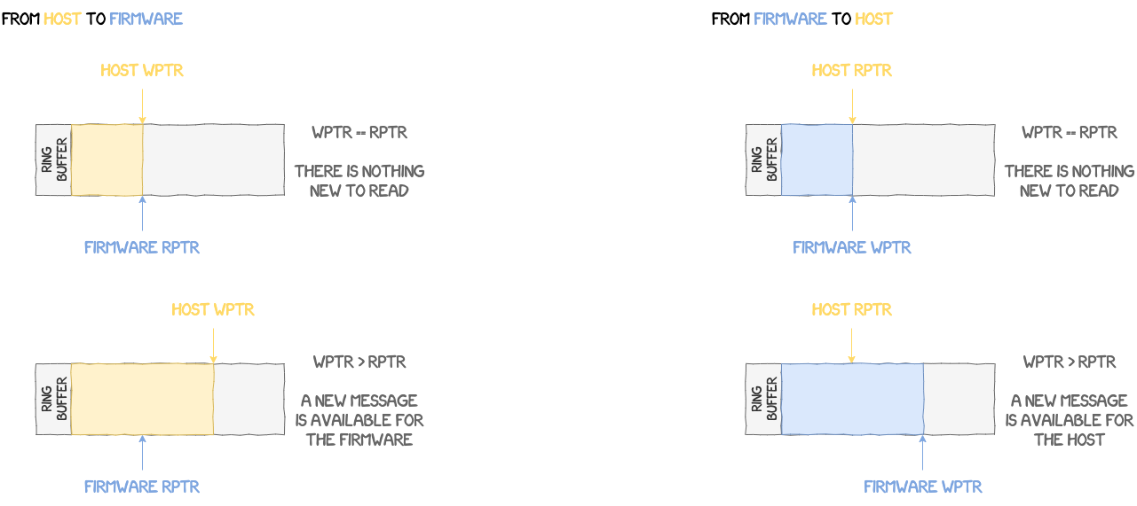
Another check performed by the NPU to verify that a message is indeed available, is to check the values in struct mailbox_ctrl.
struct mailbox_ctrl {
    u32 sgmt_ofs;
    u32 sgmt_len;
    u32 wptr;
    u32 rptr;
};
hctrl is the state of the host and fctrl the state of the firmware. These structures also store both the read and write pointers in the mailbox's ring buffer. In the case of a message sent by the AP, when both the read pointer of the firmware and the write pointer of the host point to the same location, then it means that there is no new message, all requests have already been handled because the firmware "caught up" to the host. However, if the host has sent a message, but the firmware hasn't got the chance to handle it yet, then it means the host is ahead of the firmware, i.e. its write pointer points to a location after the one pointed to by the read pointer of the firmware. The same scenario applies when it's a message sent by the NPU. Below is an illustration of this process.
Messages in the mailbox are divided into two parts:
- a header following the format of
struct message; - a payload.
struct message {
    u32 magic;
    u32 mid;
    u32 command;
    u32 length;
    u32 self;
    u32 data;
};
length represents the size of the payload and data its offset from the beginning of the mailbox's segment. For example, the low priority mailbox segment is at address 0x80000-0x1400 = 0x7ec00. If a message data in the low priority mailbox is at offset 0x60, then the address of the payload is 0x7ec60.
The message extracted is then passed to mbx_msghub_req, which is going to retrieve the command from the message and call the corresponding NCP handler. This handler performs, somewhere down the line, the actual neural processing. However, this part won't be explained in this article. One thing to note though, is that all handlers call the following functions:
-
mbx_msghub_inp: at the beginning of the handler to set the state of the message fromRESPONSE_READYtoRESPONSE_IN_PROGRESS; -
mbx_msghub_res: at the end of the handler, to fill the response with the resulting values.
The result of an operation is stored in a struct ncp_message if everything went as expected or in a struct ncp_error if an error occured. Since these two structures are pretty similar, only ncp_message is given below:
struct ncp_message {
    struct message msg;
    struct message result;
    struct mailbox_dnward *mbox;
    u32 sgmt_cursor;
    u32 _unk_38;
    u32 _unk_3c;
    u32 _unk_40;
    u32 _unk_44;
    u32 _unk_48;
    u32 _unk_4c;
    u32 _unk_50;
    u32 id;
    u32 _unk_58;
    u32 _unk_5c;
    u32 state;
    u32 _unk_64;
};
In both cases, the resulting response is passed to the function mbx_upward_issue, which is going to add the result to the list of pending responses to send to the AP. We'll get back to this function in the next section.
Upward Mailbox: Sending Messages to the AP
Now that our request has been handled and its result is available, we can detail the final steps needed to send the response back to the kernel. The mailbox responsible for this operation is the response mailbox which uses the structure given below to keep track of its state.
struct mailbox_upward {
    u32 event_id_off;
    struct event* event;
    u32 start;
    struct mailbox_ctrl *hctrl;
    struct response responses[NB_MESSAGES];
    struct response_list available;
    struct response_list pending;
};
The two lists in this structure, available and pending, are used to reference:
- available reponses that can be used to store a result;
- pending responses that are waiting to be sent to the kernel.
To add a reponse to the pending list, the function mbx_upward_issue is used. It takes an available response object, from the available list, attaches the result to it and adds it to the pending list with add_to_rsp_list. Finally it notifies the response task that a new message is available with __set_event.
We've seen before that the response task's handler is TASK_mailbox_response. It's an infinite loop that calls three functions.
mbx_upward_get: it waits for a response withwait_eventand, when one is available, takes it from the pending list and retrieves the original request's result from it.mbx_dnward_put: updates the host's read pointer to point to the next unhandled message.mbx_upward_put: writes the response and copies the payload into the response mailbox. It also updates the host's write pointer.
From the NPU Back to the Kernel
We're finally at the stage where the result has been sent and is ready to be handled by the kernel. This section backtracks the path taken by the reponse all the way back to the original request.
The mailbox is probed by the function nw_rslt_manager to check whether or not a new message has arrived. To do so, it looks at the values in the mailbox control structure we presented earlier.
int nw_rslt_manager(int *ret_msgid, struct npu_nw *nw)
{
    /* [...] */
    ret = mbx_ipc_peek_msg((void *)interface.addr, &interface.mbox_hdr->f2hctrl[0], &msg);
    /* [...] */
    ret = mbx_ipc_get_msg((void *)interface.addr, &interface.mbox_hdr->f2hctrl[0], &msg);
    /* [...] */
    ret = mbx_ipc_get_cmd((void *)interface.addr, &interface.mbox_hdr->f2hctrl[0], &msg, &cmd);
    /* [...] */
}
nw_rslt_manager is actually a callback that is called in the function npu_nw_mbox_ops_get.
struct npu_if_protodrv_mbox_ops npu_if_protodrv_mbox_ops = {
    /* [...] */
    .nw_get_result = nw_rslt_manager,
    /* [...] */
};
int npu_nw_mbox_ops_get(struct msgid_pool *pool, struct proto_req_nw **target)
{
    /* [...] */
    if (npu_if_protodrv_mbox_ops.nw_get_result)
        ret = npu_if_protodrv_mbox_ops.nw_get_result(&msgid, &nw);
    /* [...] */
}
The call to npu_nw_mbox_ops_get comes from the wrapper nw_mbox_ops_get.
static int nw_mbox_ops_get(struct proto_req_nw **target)
{
    return npu_nw_mbox_ops_get(&npu_proto_drv.msgid_pool, target);
}
Then we can see that nw_mbox_ops_get comes originates from npu_protodrv_handler_nw_processing. This functions puts the reponse into the COMPLETED queue.
static int  npu_protodrv_handler_nw_processing(void)
{
    /* [...] */
    while (nw_mbox_ops_get(&entry) > 0) {
        /* [...] */
        default:
            /* Result code already set on nw_mbox_ops_get() -> Just change its state */
            proto_nw_lsm.lsm_move_entry(COMPLETED, entry);
            handle_cnt++;
            break;
        }
        /* [...] */
    }
    /* [...] */
}
Finally, npu_protodrv_handler_nw_completed is called to handle the response in the COMPLETED list. If everything went as expected, it will run the callback that was previously set in npu_session_put_nw_req with a call to nw_mgmt_op_put_result.
static int npu_protodrv_handler_nw_completed(void)
{
    int ret = 0;
    int handle_cnt = 0;
    int entryCnt = 0;   /* For trace */
    struct proto_req_nw *entry;
    struct session_ref_entry *session_ref_entry;
    int transition;
    char stat_buf[TIME_STAT_BUF_LEN];

    /* Process each element in REQUESTED list one by one */
    LSM_FOR_EACH_ENTRY_IN(proto_nw_lsm, COMPLETED, entry,
                /* [...] */
                switch (entry->nw.cmd) {
                case NPU_NW_CMD_LOAD:
                    /* [...] */
                    transition = 1;
                    break;
                /* [...] */
        }
        /* Post result if processing can be completed */
        if (transition) {
            /* [...] */
            if (!nw_mgmt_op_put_result(entry)) {
                npu_uinfo("(COMPLETED)NW: notification sent result(0x%08x)\n",
                    &entry->nw, entry->nw.result_code);
            }
            /* [...] */
        }
    ) /* End of LSM_FOR_EACH_ENTRY_IN */
    /* [...] */
}
This callback notifies the driver that the response is ready and that the user can now access the result of the computation, thus ending the transaction between the kernel and the NPU.
Conclusion
In this article, from a single binary we've managed to get a pretty good understanding of the operating system implemented by Samsung for their Neural Processing Unit. There is still a lot of ground to cover, such as NCP handlers or neural computation routines in general, but at least we know the internals of the core components of the OS as well as how it interacts with the Android kernel. The next article in this series will highlight some vulnerabilities we found and exploited in the NPU to attack the kernel.
References
- Exynos - Wikipedia
- Samsung NPU (Neural Processing Unit) memory corruption in shared memory parsing - Project Zero's Bug Tracker
- SM-G980F G980FXXS5CTL5 Firmware - SamMobile
- Mobile Phone Source Code - Samsung Open Source